Summary:Shunt resistors are special types of current sensors that send a millivolt output to an indicating i...
Shunt resistors are special types of current sensors that send a millivolt output to an indicating instrument, or other device, in proportion to the current flowing through the shunt. They are often used in power meters, but can be found in other applications as well.
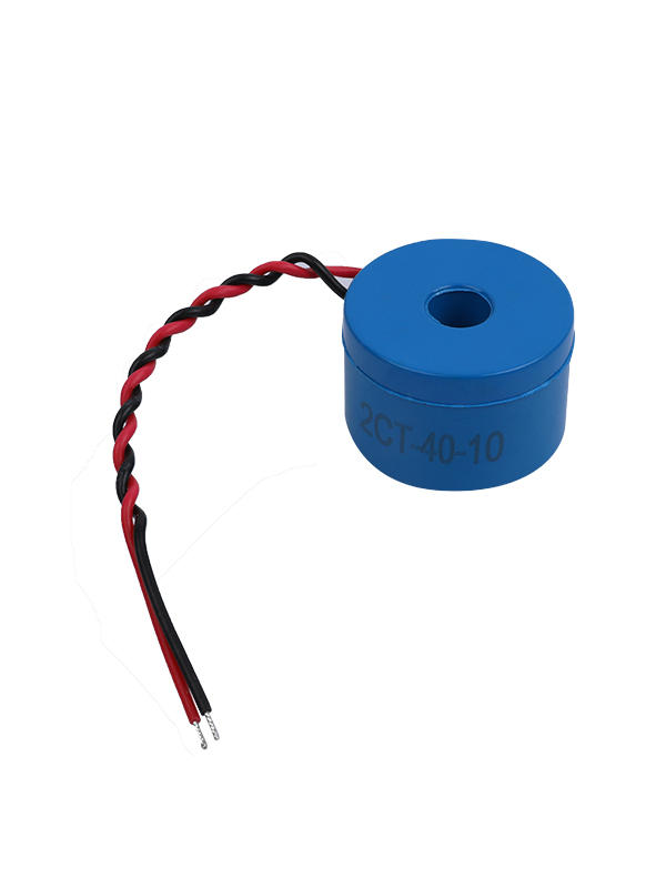
A shunt is usually comprised of two conductive metals on the sides and connected by a band of specialized metal, called manganin, that is designed to prevent the flow of current through it from causing the shunt to short out or burn out. They are commonly used in DC (direct current) instruments to extend the range of an indicating instrument when the measured current is too high for the meter to measure directly, usually in the 50-ampere range.
The shunt can be connected to a line or neutral, depending on the application. In most energy meters, the shunt is referenced with respect to the line voltage to avoid common-mode voltage issues and heating issues that arise when using the shunt in a single-phase meter.
It is important to select the shunt resistance based on the application and the load that the shunt is being used with, in order to minimize the power dissipation of the shunt. It is also important to consider that a shunt is not an inexhaustible source of energy, and may be subject to the effects of magnetic tampering or heating issues.
This type of shunt is not recommended for use in the meter’s internal circuitry, which must be shielded from external magnetic field attacks. However, it can be useful in detecting tampering on the meter’s AC power supply.
One tampering technique is to remove the neutral connection from the meter, which will cause the meter to be unable to detect voltage. This will not affect the RMS power readings or active power readings, but it may affect the meter’s ADC.
Another tampering technique is to change the order of the shunt input terminals on the J25 header, which will change the ADC offsets in the current channels. This change in the ADC offsets can be detected by an offset calibration function that is used by the meter’s PC GUI to subtract out most of the ADC offsets from both current channels. This is done to improve the matching of the line and neutral ADC channels, which have significantly different ADC offsets due to their different gains being used on them.
These offsets can be detected by the meter’s ADC, which will then trigger the meter to enter current-detection mode. The meter’s PC GUI will then use this information to trigger an alarm when the ADC’s corresponding current-detection registers change in value.
In this scenario, the meter’s main AC/DC power supply is not functioning and a backup power supply, such as a battery, must be used to power the meter. This can be distinguished from a power outage situation by the presence of line current on the meter, which will not be present if the meter’s neutral connection has been removed.

 China Manganin Shunts Manufacturers
 English