Summary:Three phase meter current transformer is an important part of power metering system. It is used to m...
Three phase meter current transformer is an important part of power metering system. It is used to measure the voltage and current of the high voltage power meter. It is a special electrical equipment, and it has many advantages in the power metering industry.
How it Works:
A current transformer converts a high primary current into a low secondary current value to reduce its size, weight, and cost. It is used in a wide range of applications including power circuitry, instrumentation in the avionics, automotive, and military industries as well as telecommunications.
Typical CT's are rated at a ratio of 100/5, so for 500 amps in the main primary conductor, the secondary current is 5 amps.
This relationship allows the CT to step down a high primary current into a lower primary current, which is easier to measure with a standard ammeter. The resulting secondary current value can be measured with a wattmeter, energy meter, or power factor meter.
Common CT sizes include small split-core type units (with removable sections) for temporary connection, and larger ring type units that can be attached around a wire without disconnecting it. There are also special types of CT used in measuring instruments that have a clamp opening to measure current around conductors or bus bars, such as Rogowski coils (see below).
What's the Output?
The output of the meter should be chosen with care to ensure it is compatible with the current transformer. Some popular output options include 333mV, 5A or 80mA.
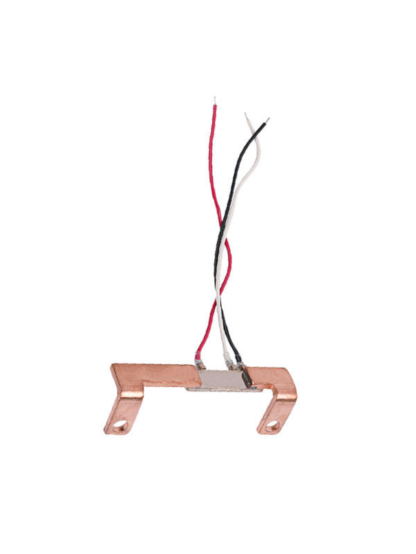
In most cases, a resistive shunt is preferred for measuring phase current because it does not have an inverse relationship with the secondary current as the CT does. Shunts are available in single and multi-phase models and can be either wired directly to the meter or plugged into an adapter.
Shunts have an advantage in that they are more accurate than CT's and are able to measure DC as well as AC, but they are not a good choice for the high currents often found in the power industry.
Besides, they have an inherent 90 degree phase shift. This means they are not directly compatible with most meters and other measurement devices.
When using a shunt in place of a current transformer, be sure to check with your meter manufacturer. They may be able to compensate for the phase shift or provide an alternative topology that will not introduce any errors.
The most important thing to remember is that a current transformer is designed to be proportional. When the primary and secondary currents are in the correct ratio, the metering device will be accurate within its rated range.
There are other considerations, including loads, external electromagnetic fields, phase change, capacitive coupling between the primary and secondary windings, resistance between the primary and secondary, temperature, burden, and core magnetizing current. The resulting error can be significant and lead to inaccurate measurements of power and energy usage. This can result in a higher than expected electricity bill.

 China Manganin Shunts Manufacturers
 English